ZTX IP CONTROLLER
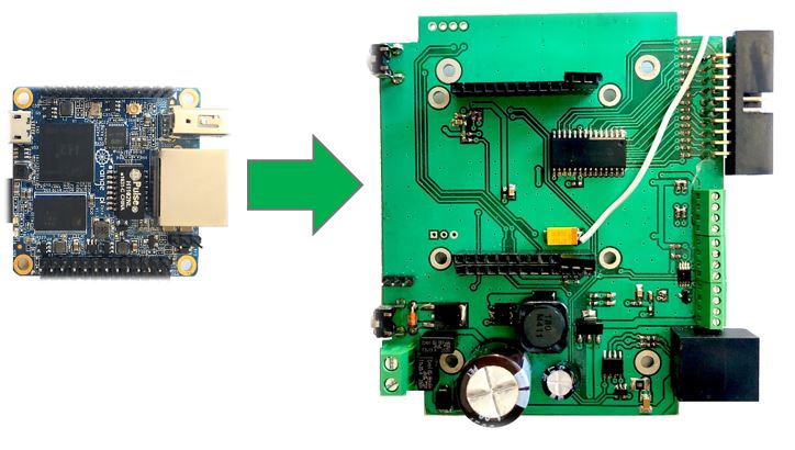
Orange Pi Zero
The Orange Pi Zero 512Mb mini-computer is a miniature single-board computer based on Allwinner H2 + processors and has four Cortex A7 computing cores with a clock frequency of up to 1.2 GHz. open source. It can work on Android 4.4, Ubuntu, Debian. It has 512 MB of DDR3 SDRAM RAM. Also, this minicomputer is equipped with the Mali-400MP2 graphics accelerator, which allows you to play 4K video in H.265 / HEVC format with a playback frequency of up to 30 frames per second and supports microSD memory cards with a frequency of up to 64 gigabytes. The mini Pi Orange Zero 512Mb computer is perfect for building embedded control systems and control systems. The following operating systems are supported: Ubuntu MATE, Debian, Armbian and others. The computer is powered by a 5V 2A power supply through a microUSB connector. The list of interfaces supported by Orange Pi Zero:
- ETHERNET
- GPIO
- SPI
- I2C1
- UART
- USB
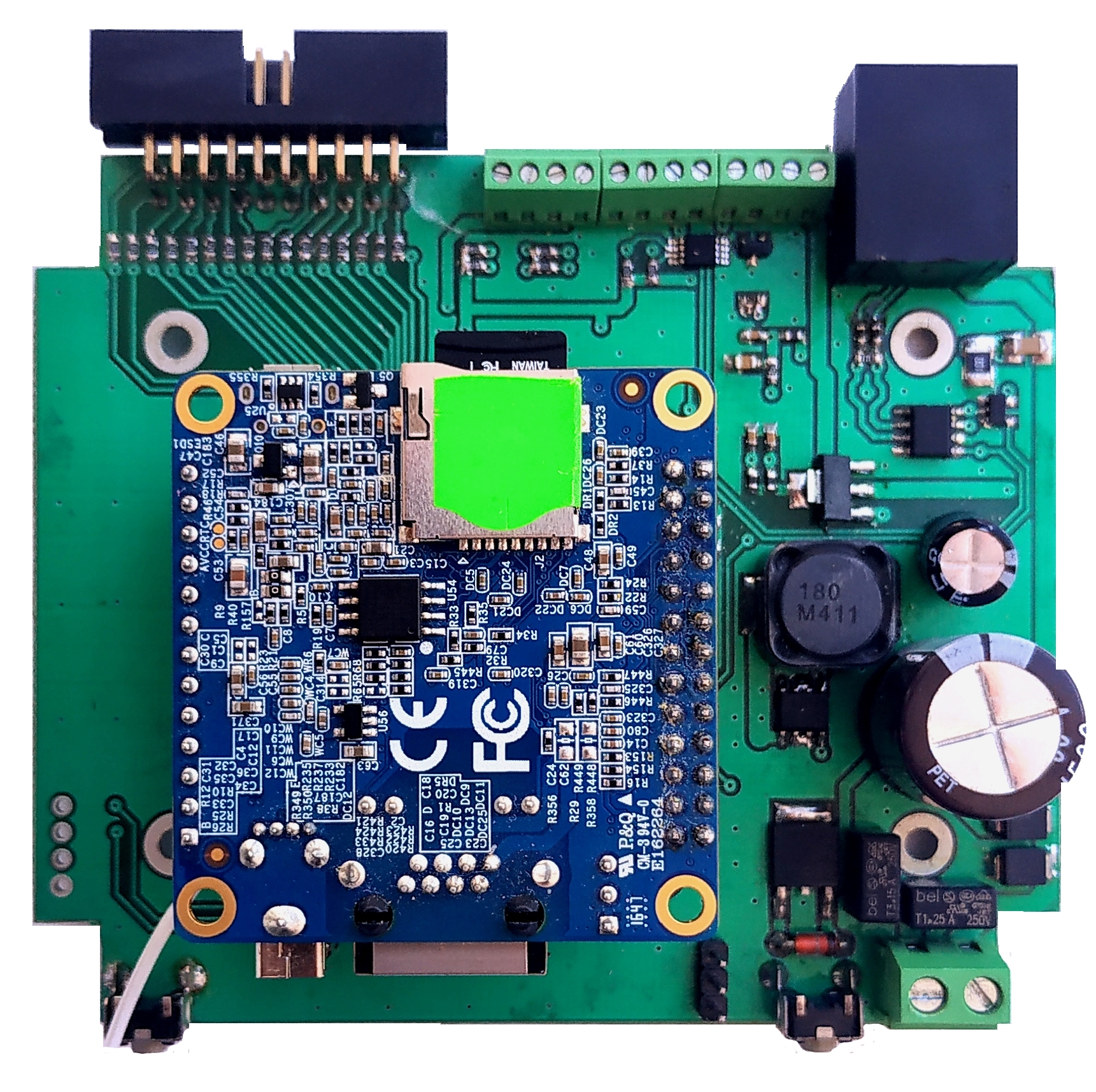
Using these interfaces, the minicomputer can communicate and control a huge number of different devices, sensors. Board Load Control was created specifically for the Orange Pi Zero. It is very easy and easy to install a mini PC. The list of interfaces supported by the Load Control Board:
- ETHERNET
- GPIO
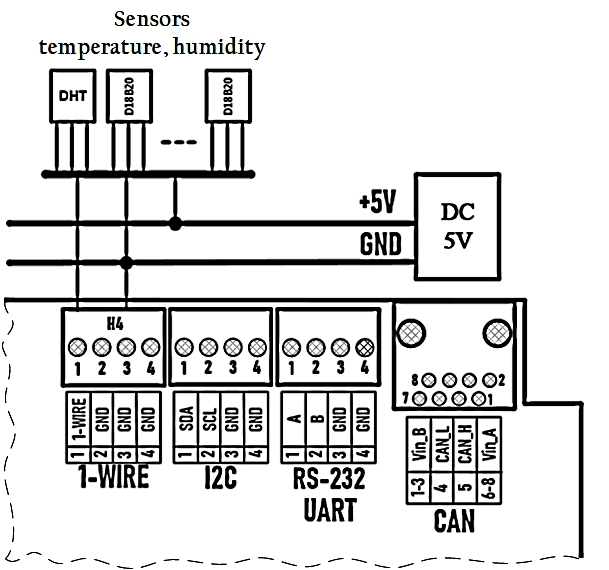
- 1-WIRE
- USB
- I2C
- CAN
- RS-232
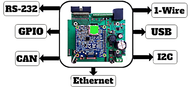
Topology of the Load Control Board
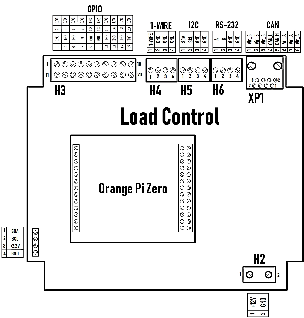
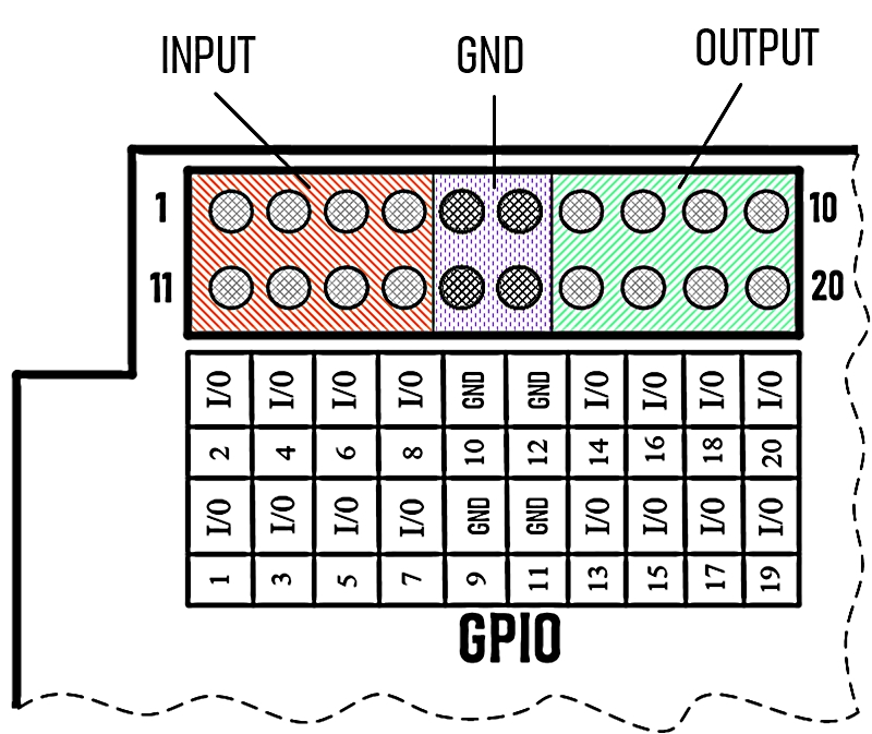
The “Load Control” board contains the MCP23016 port expander. It is connected to the I2C bus of the Orange Pi Zero. Using the “i2c-tools” utility via the “I2C” bus, you can manage this port expander. All inputs / outputs of the MCP23016 are output to the “H3” connector of the board. The MCP23016 chip has 16 independent inputs / outputs that can be configured as you like, for example: 16 inputs, 16 outputs, 8 inputs/8 outputs, etc.
MCP23016
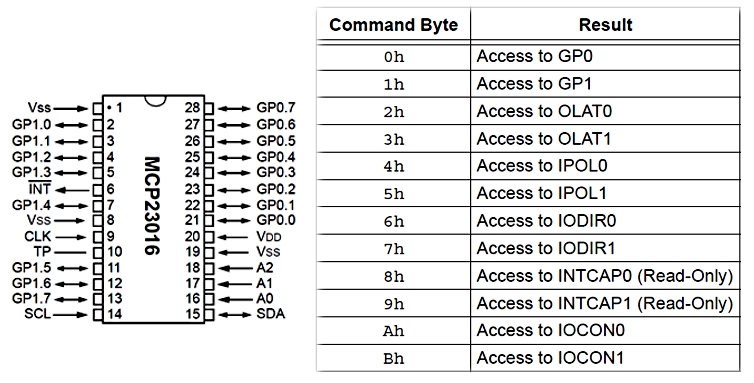
In order to manage the port expander, first we need to set the operation mode (Input / Output). To do this, we need to write a logical “1” or a logical “0” in the “IODIR (0/1)” registers.
- "1" - Input mode;
- "0" - Output mode.
In order to manage the MCP23016 ports themselves, you need to write the corresponding pin configuration in hexadecimal form depending on the need in the registers “GP (0/1)”. An example of writing to registers:
i2cset -y 1 0x20 0x06 0x00
- i2cset -y 1 - command to write to “i2c1”.
- 0x20 is the address of the “i2c” device.
- 0x06 - register address IODIR0.
- 0x00 - pin addresses.
Example of reading from the registers GP (0/1):
i2cget -y 1 0x20 0x00
- i2cget -y 1 - command to read from “i2c1”.
- 0x20 is the address of the “i2c” device.
- 0x06 - register address GP0.
An example of connecting buttons, sensors, devices to the board Load control

Example of connecting temperature and humidity sensors
MCP23016 Port Expander I/O
Initially, in MC23016 the GPIO_1 port is configured as "INPUT", and the GPIO_0 port is configured as "OUTPUT" (8 inputs, 8 outputs).
Orange Pi Zero. Software.
The system was installed on the Orange Pi Zero: “Armbian_5.90_Orangepizero_Debian_buster_next_4.19.57”. Login Options:
Login: root
Password: root1234
The interface was pre-configured: GPIO, USB, I2C, 1-WIRE, CAN.
In the folder "home / example /" are examples of scripts:
- "oled_display.py" - an example of display control (OLED DISPLAY MODULE 128x64 0.96 INCH 4PIN), displaying the boot status of the Orange Pi Zero system
- "dht_example.c" - an example of reading temperature and humidity sensors "DHT"
- "dht_example" - compiled executable file.
- "ds18b20_example.py" - an example of reading data from one_wire temperature sensors "D18B20".
- "serial_read.py" - an example of reading a serial port (RS-232).
- "serial_write.py" - an example of writing to the serial port (RS-232).
In the folder "home /" are examples of scripts:
- "ds18b20_mqtt.py" - an example of reading and sending MQTT data to IOBroker "one-wire" temperature sensors "D18B20"
- "dht_example" - an example of reading temperature and humidity sensors "DHT"
- "dht_mqtt.py" - an example of reading data from temperature and humidity sensors "DHT" through the script "dht_example" and sending data via MQTT to IOBroker.
- "mcp23016_mqtt.py" - an example of port management of the I2C chip "MCP23016" through MQTT in IOBroker vis. Configured: GPIO_1 - INPUT, GPIO_0 - OUTPUT.
- "can_mqtt.py" - an example of reading / writing CAN bus. The script is written under the ZTX_RELAY_BOARD module.
Installed by IOBroker. IOBroker was installed in the system, with pre-adjustment for reading DHT11, D18B20 sensors on MQTT and outputting data from the sensors to the main IOBroker vis screen. In IOBroker vis, the current state of the ports of the mcp23016 microcircuit is displayed, which is displayed in the form of "bulbs", and 8 are also displayed switches that control the GPIO_0 ports. Under the ZTX_RELAY_BOARD device, IOBroker vis displays (8 buttons) controls, the current state of the ports displayed as "light bulbs".
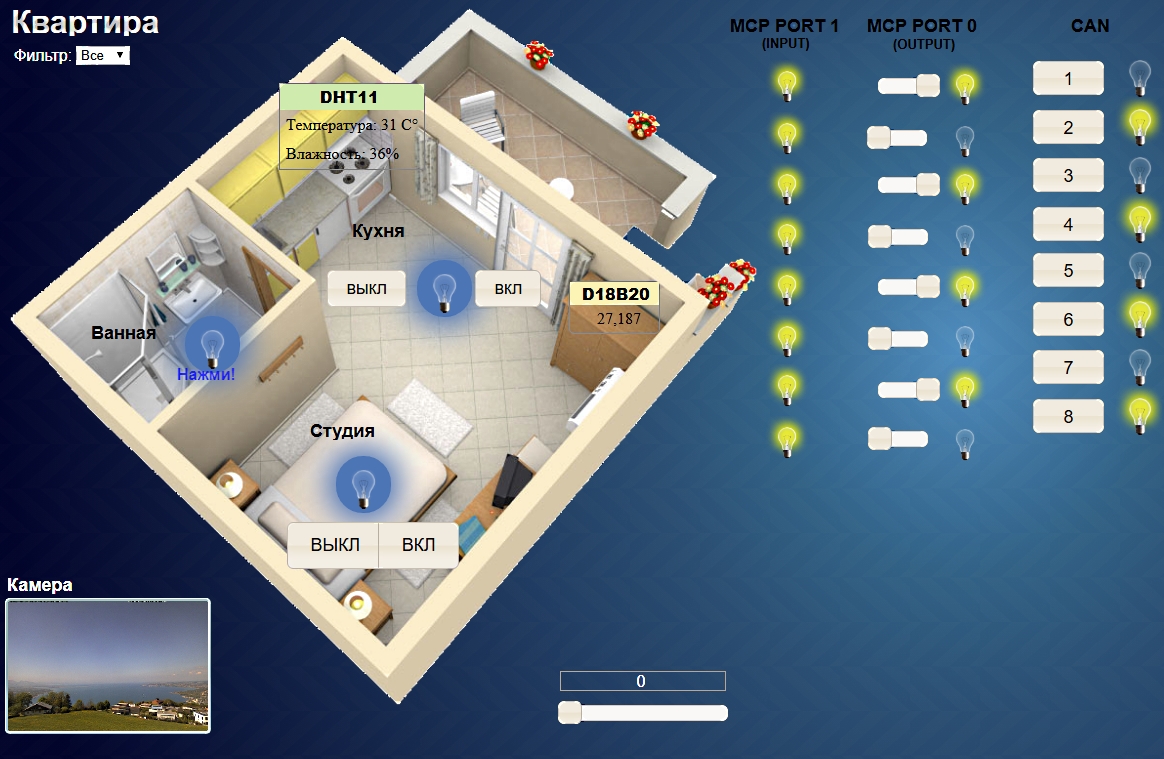
Image Link for Orange Pi Zero:
https://drive.google.com/open?id=1VsjcYONh33YHjJgRBBUj8eQGVNDqsJXB
Link to the project board LODCONTROL (Altium Designer):
https://drive.google.com/open?id=1eswctbBn8OdKM3PahSVlwfSGJnC4jD-w
Gerber:
https://drive.google.com/open?id=1-Glb6r7VXzynMiEbGvqNBCZyAI__i-gK
| Name | Size | # Downloads |
|---|---|---|
| AD_Library.PcbLib | 2.64 MB | 419 |
| LoadControl.SchDoc | 390.5 kB | 433 |
| LoadControl1.PcbDoc | 2.28 MB | 462 |
| PcbLib1.PcbLib | 842 kB | 411 |
| Schlib1.SchLib | 166.5 kB | 413 |
| orange.SchDoc | 876 kB | 428 |
| LoadControl1.GBL | 99.2 kB | 377 |
| LoadControl1.GBO | 1.36 MB | 380 |
| LoadControl1.GBP | 8.07 kB | 393 |
| LoadControl1.GBS | 10.93 kB | 358 |
| LoadControl1.GM2 | 504 B | 348 |
| LoadControl1.GTL | 94.01 kB | 382 |
| LoadControl1.GTO | 631.52 kB | 398 |
| LoadControl1.GTP | 4.31 kB | 376 |
| LoadControl1.GTS | 7.16 kB | 396 |
| LoadControl1.TXT | 6.37 kB | 320 |
| CIRCUIT_BOARD_LOADCONTROL.pdf | 152.3 kB | 405 |
