With TP4056 battery charger, Bluetooth socket, I2C socket and NRF24l01+ socket
TP4056 battery charger Battery voltage and charge current are reported on ADC7 and ADC6.
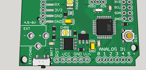
Charge current is limited to 400mA and can be changed to another value by changing one resistor.
float readVcc()
{
  signed long resultVcc;
  float resultVccFloat;
  // Read 1.1V reference against AVcc
  ADMUX = _BV(REFS0) | _BV(MUX3) | _BV(MUX2) | _BV(MUX1);
  delay(10);                           // Wait for Vref to settle
  ADCSRA |= _BV(ADSC);                 // Convert
  while (bit_is_set(ADCSRA,ADSC));
  resultVcc = ADCL;
  resultVcc |= ADCH<<8;
  resultVcc = 1126400L / resultVcc;    // Back-calculate AVcc in mV
  resultVccFloat = (float) resultVcc / 1000.0; // Convert to Float

  return resultVccFloat;
}

const int current = A6;
const int lipo = A7;


float vout = 0.0;
float vin = 0.0;
int value = 0;

void setup()
{
  Serial.begin(9600);
}

void loop()
{
  float napetost = readVcc();

  float tok = ((analogRead(current) * napetost / 1024 ) * 1200) / 3; // convert the ADC value of charge current to miliamps
  float baterija = ( analogRead(lipo) * napetost / 1024 ) * 2; // measuring battery voltage

  Serial.print("Vcc = ");
  Serial.print(napetost);
  Serial.println("V");
  delay(400);
  Serial.print("Charge current = ");
  Serial.print(tok);
  Serial.println("mA");
  delay(400);
  Serial.print("Battery voltage = ");
  Serial.print(baterija);
  Serial.println("V");
  delay(400);
  Serial.println("----------------------------");
  delay(2000);
}
/*
Improving accuracy:
To do so, simply measure your Vcc with a voltmeter and with our readVcc() function. Then, replace the constant 1107035L with a new constant:
scale_constant = internal1.1Ref * 1024 * 1000
where
internal1.1Ref = 1,1 * Vcc1 (per voltmeter) / Vcc2 (per readVcc() function)
Example:
For instance, I measure 3,43V from my FTDI, the calculated value of Vref is 1,081V.
So (1,081 x 1000 x 1024) = 1107034,95 or 1107035L rounded up.

Use smoothing example from IDE to smooth the data from ADC.
*/
NRF24l01+ and Bluetooth radio socket
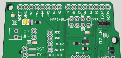
CE and CSN pins of the NRF24 socket are connected to digital pins D7 and D8. There is a 10uF capacitor connected across Vin and GND of the socket. Bluetooth socket has RX and TX pins connected to digital pins D5 and D6.
LDO voltage regulator
The board comes with an MPC1702 3.3V as a standard, which has a low 2uA quiescent current.
Dual socket with SDA and SCL lines
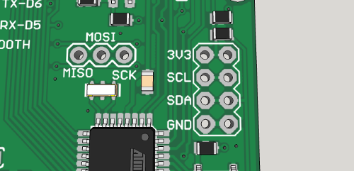
and 10k pull-up resistors for external I2C components, connected to analog inputs A4 and A5.
Other features
N-channel MOSFET for regulating power to external loads. The gate is connected to digital pin D3 of the ATmega328.

Low power (2mA) LED diodes that are connected via solder jumpers. Jumpers need to be soldered in.
On the back of the board there is place for: BME280, a digital temperature, humidity and pressure sensor, an additional EEPROM, and SI114x ambient / UV light sensor.
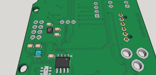
There are few such boards available and none with this kind of versatility.
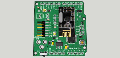
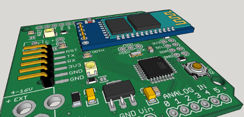
Fully Arduino compatible with Arduino PRO Mini 3.3V @ 8MHz bootlader.
This board is perfect for low-power applications. Identical - small - footprint as Arduino PRO. Only better. It is intended for sensor applications and can be used as an universal board for sensor node networks. Dimensions are 2 inch x 2.1 inch.
| Name | Size | # Downloads |
|---|---|---|
| IoT_Pro_01.brd | 178.37 kB | 896 |
| IoT_Pro_01.sch | 586.3 kB | 886 |