RGBW Lighting
I love the new possibilities that modern leds provide (cheap, efficient, small, ...) and I wanted a nice project to play with for my home automation. As I could only find a dimmer for one-color-leds and domoticz and mysensors recently added support for rgb(w) lighting I started to build a control pcb for just that.
I got some help here.
Hardware
The board
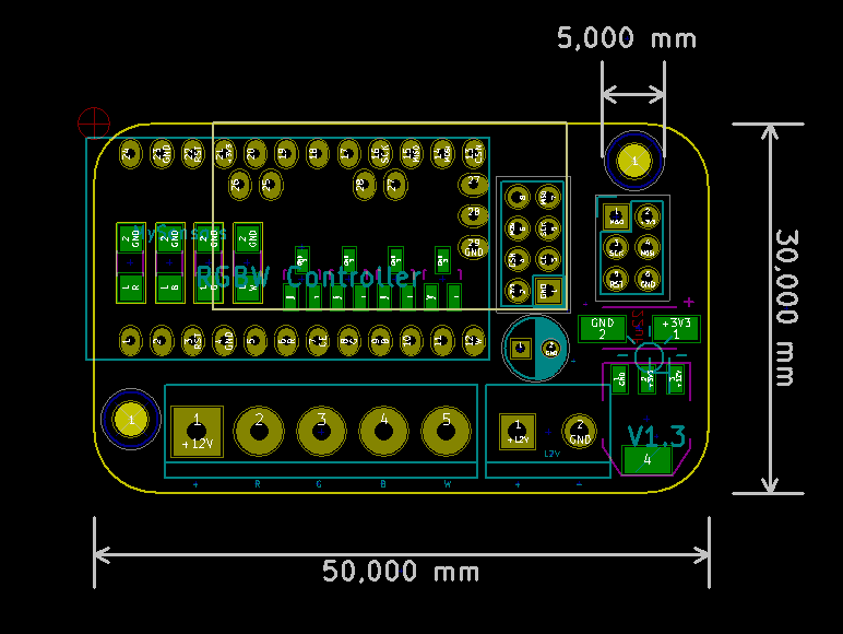
The board should be relativly easy to build and use and shouldn't be too big. The maximum size was 5x5cm as thats what cheap pcb manufactures mostly support. In the end I used a 30 by 50mm board with rounded edges and 2 mounting holes.
The components
I tried to use small but easy to solder components. IRML2502 mosfets in a smd formfactor are used to control the channels of the leds. They are pretty small but one can still solder them by hand without too many problems. I had an earlier version where I used through hole mosfets but these take up a lot of space. An AMS1117 is used to generated the 3.3V from the 12V (led power) input. I tried a buckconverter for more efficiency but these need a lot of filters otherwise the radio doesn't work anymore. As the whole thing doesn't draw too much power a linear regulator should be sufficient. The core is an arduino pro mini. That one is cheap and already has all components it needs to run. Perhaps I will create another version with just the atmega 328P but at the moment this is the easiest solution. Beside the NRF24L01+ radio I and some passive components I also added an ISP programmer 6-pin port to be able to change the program without using the serial connection if need be.
The enclosure - Added 08.2018
I recently got a 3d printern and so I started to design and print a custom enclosure for my RGBW controller(s). It features labels on the front, a mounting point for cable management on the side and standoffs with screw holes for the pcb on the inside. The front has a matching cutout to connect all cables otherwise its closed. The lid just clips in and can be (re)opened at any time.
The cases work great for me you only need to trim the headers on the pro mini (if they are soldered at all). The stl files can be found here and on my github repo if you want to print some enclosures too.
Software
At the moment the software relies on domoticz as a controller or some software that sends the same kind of information. The program stores the current target level for the leds which it gets from domoticz and then fades from its current values to the target ones. As the human eye doesn't see changes in brightness linearly I tried to use non linear scaling for but that doesn't seem to work yet.
Update: I just added a newer version of my sketch that is based on MySensors 2. The most update-to-date version can always be found in my github repo.
Mounting
I build a custom lighting system for my living room which uses this controller. It's still work in progress but I will try to upload some pictures soon.
TODOS
- Make non linear fading work
Errors
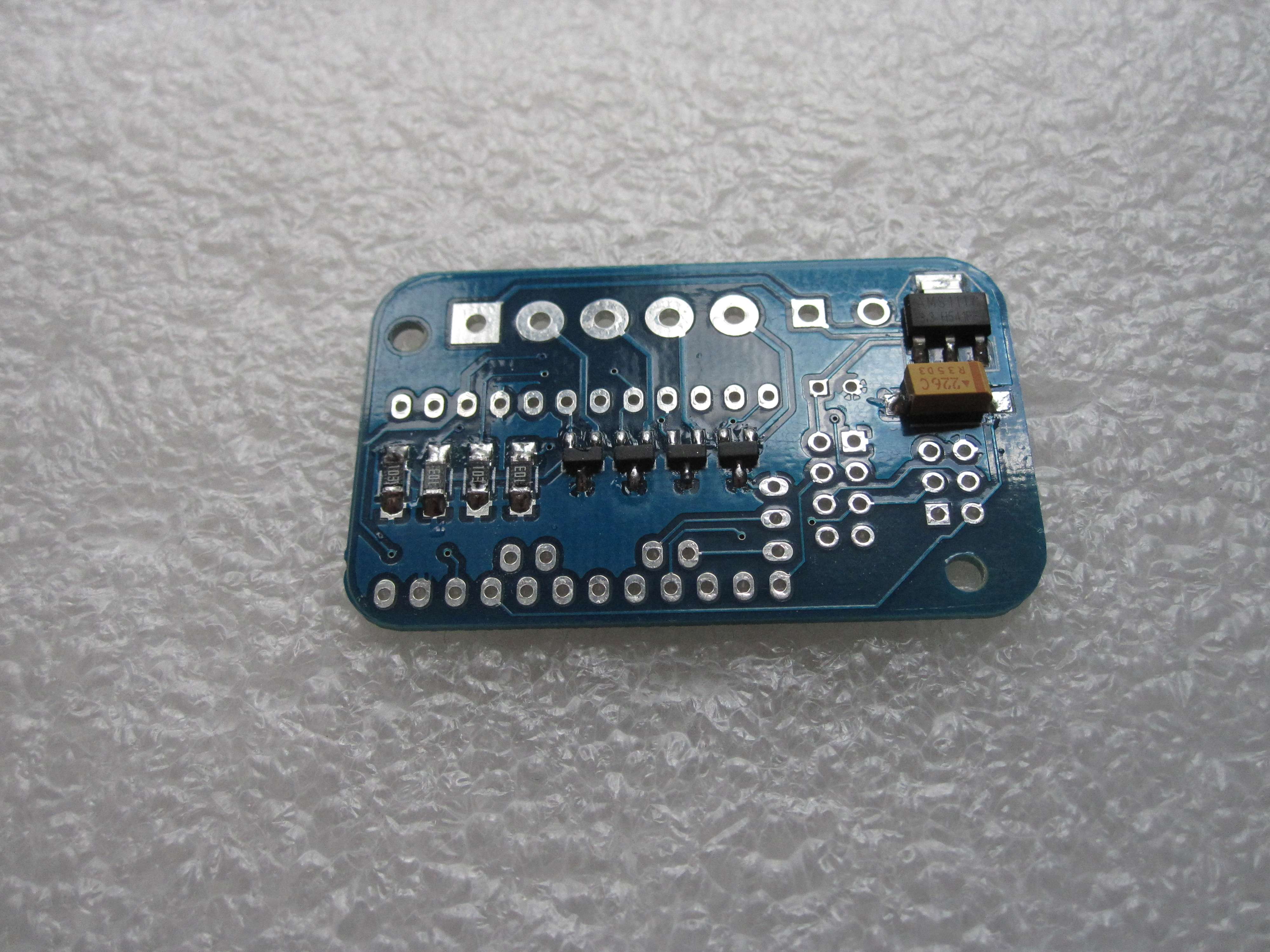
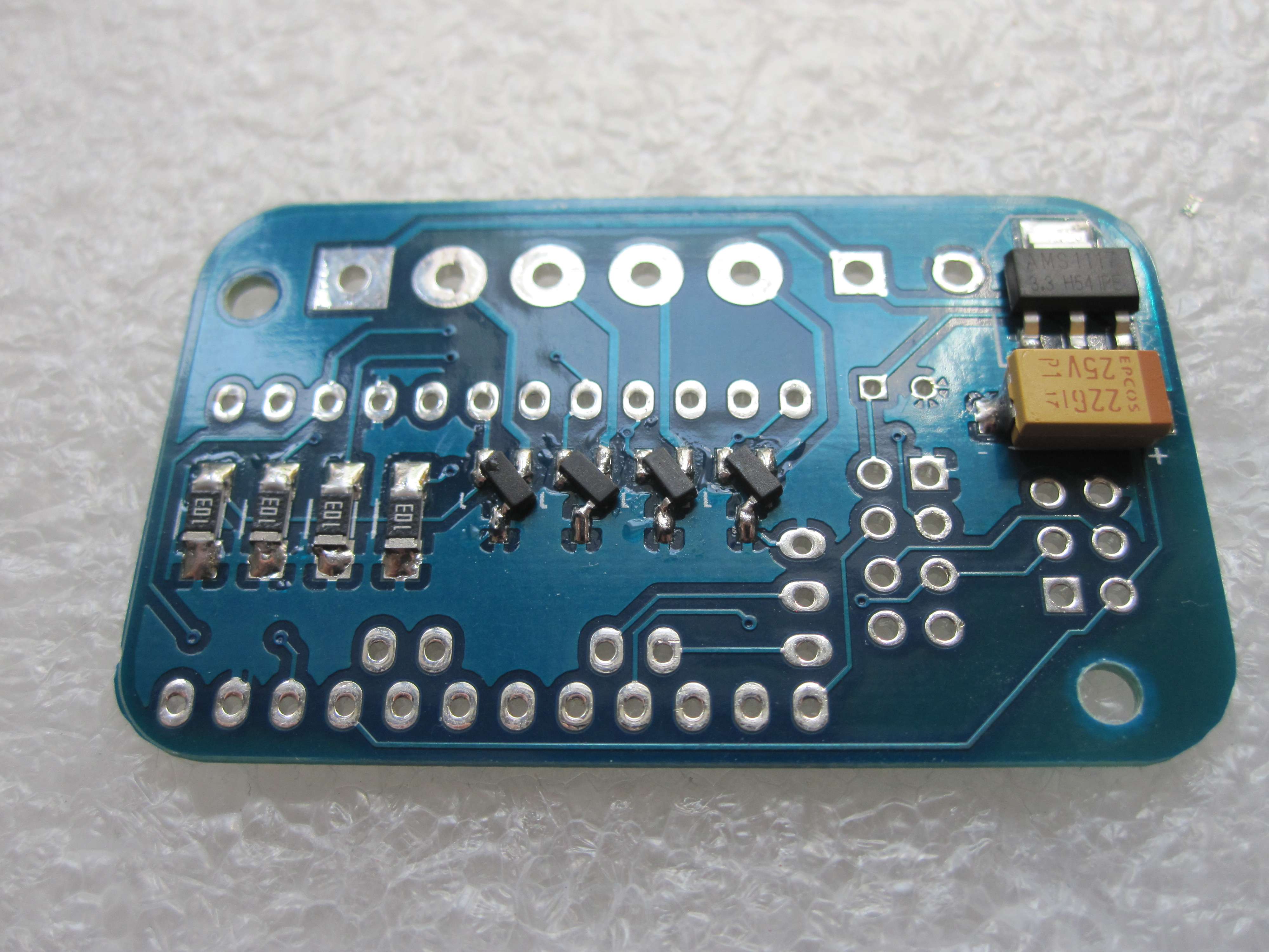
The old version (that I have tested and where these pictures are from) had an error where I switched outputs for the mosfets! They have to be rotated to work! In the newest (gerber) files in the linked github repo I fixed these mistakes. Although I haven't tested these new boards (yet) they should work without this fix now.
Wrong:
 Right:

Update: 5 RGBW controllers using the first generation (with the switched mosfets) have been running here for months now without error.
Update2: They have been running for about 2 years now mostly without problems. The only disadvantage is that my Mysensors network overall is quite "slow" (~1s reaction time). I am currently experimenting with Wifi RGBWW controllers (H801) so there wont be to many more updates to this project
PCB
The pcb can be bought here. Read the error part above!
| Qty | Value | Device | Package | Parts | Description | MF | MPN | Aliexpress or Ebay link |
|---|---|---|---|---|---|---|---|---|
| 1 | Arduino Pro Mini | |||||||
| 1 | NRF24L01+ | |||||||
| 1 | 6 Pin Connector | |||||||
| 4 | IRLML2502 | Mosfet | SOT-23 | |||||
| 1 | AMS1117 | |||||||
| 1 | 22uF tantal capacitor | |||||||
| 1 | 47uF capacitor | Radial | ||||||
| 4 | 10k resistor | SMD 1206 | ||||||
| 1 | 5 pin screw terminal | |||||||
| 1 | 2 pin screw terminal |
| Name | Size | # Downloads |
|---|---|---|
| RGBWController-B.Cu.gbl | 58.38 kB | 2870 |
| RGBWController.drl | 1.15 kB | 3108 |
| RGBWController.kicad_pcb | 90.39 kB | 3022 |
| RGBWController.kicad_pcb-bak | 65.71 kB | 3190 |
| RGBWController.sch | 14 kB | 3163 |
| RGBWController-B.Mask.gbs | 2.77 kB | 3035 |
| RGBWController-Edge.Cuts.gm1 | 789 B | 2862 |
| RGBWController-F.Mask.gts | 1.97 kB | 2879 |
| RGBWController.net | 14 kB | 3067 |
| RGBWController.pdf | 61.26 kB | 2575 |
| RGBWController-B.SilkS.gbo | 2.09 kB | 2957 |
| RGBWController-F.Cu.gtl | 4.59 kB | 3023 |
| RGBWController-F.SilkS.gto | 14.03 kB | 3058 |
| PCB.pdf | 18.83 kB | 1821 |
| rgbwCaseTopV2.stl | 53.01 kB | 2510 |
| rgbwCaseBottomV2.stl | 361.21 kB | 2599 |
| Name | Size | # Downloads |
|---|---|---|
| RGBWDimmer.ino | 6.73 kB | 4125 |
| RGBWDimmerV2.ino | 6.97 kB | 4104 |
