Sensor board w/ LTC4079 solar MPPT battery charger and NRF24l01+ radio socket
Charger IC has a complete constant current, constant voltage algorithm. It is a low quiescent current, high voltage linear charger for most battery chemistry types including Li-Ion/Polymer, Lead-Acid or NiMH battery stacks up to 60V. The maximum charge current is 100mA, set with a resistor. The battery charge voltage is set using a resistor divider. If no special instructions are made, the charge voltage is set to 4.2V.
Quiescent current while charging is 4µA
Ultralow battery drain when charged IBAT < 0.01µA
The LTC4079 charges the backup battery while greatly extends battery life. It lets you monitor voltages and charging current. The power source is a small, 5V - 20V solar cell. Connections:
analog input A7 on ATmega 328 is /CHRG signal from LTC4079
analog input A0 on ATmega328 is battery voltage
analog input A2 is solar cell voltage
analog input A6 is charge current
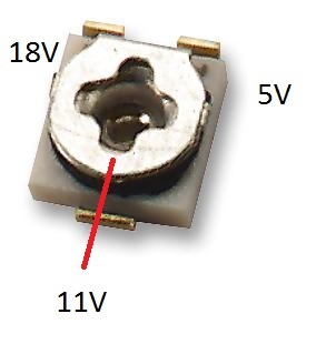
The 1Mohm trimmer potentiometer is used to determine the MPPT (multi point power tracking) point of the solar cell - to maximize its power. At shipping it is set to around 500kOhm, which sets the MPPT voltage of the solar cell to around 11V. Range is from 5V to 18V.
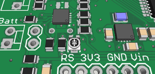
Setting the trimmer:
Voltmeters on both battery and solar cell connections are connected to analog inputs A0 and A2 on the ATmega328p. The voltage divider resistors on battery pins are equal, so the measured voltage is double the shown voltage. And the voltage divider resistors on solar cell pins are 47k over 10k. Take a look at the code example for measurement equation.
Other features on the board:
NRF24l01+ radio socketNRF24 socketwith CE and CSN pins connected to digital pins 7 and 8 ( you use RF24 radio(7, 8); in Arduino code). There is a 4.7uF capacitor connected across Vin and GND of the port NRF24
High efficiency buck-boost DC-DC regulator
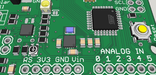
Power supply comes from a TPS63031, a 3.3V DC-DC buck-boost converter. It has low power consumption, while delivering at least 500mA in boost mode. Its efficiency is over 90% (at 10mA output, Vbat = 3.6V). Converter works with battery voltages which are below (min 1.8V), equal or higher then the output 3.3V voltage. It also has a power save mode for light loads.
A socket with SDA and SCL lines and 10k pull-up resistors for external I2C components, connected to A4 and A5
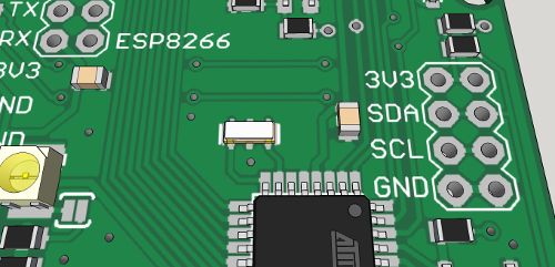
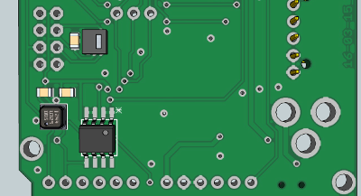
On the back, there is space for BMP180, HTU21 or SHT21 and for an EEPROM.
3amp 30V n-channel MOSFET
for regulating external components such as solenoids. The gate is connected to D3 and the output is protected with a Schottky diode.
Low power (2mA) LED diodes
that are connected via solder jumpers. Jumpers need to be soldered in. There are few such boards available and none with this kind of versatility. Fully Arduino compatible with Arduino PRO Mini 3.3V @ 8MHz bootlader.
Code example:
float readVcc()
{
signed long resultVcc;
float resultVccFloat;
// Read 1.1V reference against AVcc
ADMUX = _BV(REFS0) | _BV(MUX3) | _BV(MUX2) | _BV(MUX1);
delay(10); // Wait for Vref to settle
ADCSRA |= _BV(ADSC); // Convert
while (bit_is_set(ADCSRA,ADSC));
resultVcc = ADCL;
resultVcc |= ADCH<<8;
resultVcc = 1126400L / resultVcc; // Back-calculate AVcc in mV
resultVccFloat = (float) resultVcc / 1000.0; // Convert to Float
return resultVccFloat;
}
int current = A6;
int cell = A2;
int lipo = A0;
int CHRG = A7;
float vout = 0.0;
float vin = 0.0;
float R1 = 47000.0; // resistance of R1
float R2 = 10000.0; // resistance of R2
int value = 0;
void setup()
{
Serial.begin(9600);
}
void loop()
{
float napetost = readVcc();
value = analogRead(cell);
vout = (value * napetost) / 1024.0;
vin = vout / (R2/(R1+R2));
if (vin<0.09)
{
vin=0.0;
}
float tok = ((analogRead(current) * napetost / 1024 ) *250) / 3.3; // convert the ADC value to miliamps
float baterija = ( analogRead(lipo) * napetost / 1024 ) * 2; // measuring battery voltage
int polnjenje = analogRead(CHRG);
Serial.print("Vcc = ");
Serial.print(napetost);
Serial.println("V");
delay(400);
Serial.print("Charge current = ");
Serial.print(tok);
Serial.println("mA");
delay(400);
Serial.print("Solar cell voltage = ");
Serial.print(vin);
Serial.println("V");
delay(400);
Serial.print("Battery voltage = ");
Serial.print(baterija);
Serial.println("V");
delay(400);
Serial.print("CHRG = ");
Serial.println(polnjenje);
Serial.println("----------------------------");
delay(2000);
}
/*
Improving accuracy:
To do so, simply measure your Vcc with a voltmeter and with our readVcc() function. Then, replace the constant 1107035L with a new constant:
scale_constant = internal1.1Ref * 1024 * 1000
where
internal1.1Ref = 1,1 * Vcc1 (per voltmeter) / Vcc2 (per readVcc() function)
Example:
For instance, I measure 3,43V from my FTDI, the calculated value of Vref is 1,081V.
So (1,081 x 1000 x 1024) = 1107034,95 or 1107035L rounded up.
Use smoothing example from IDE to smooth the data from ADC.
*/
This board is made for solar powered applications with batteries as backup. Identical - small - footprint as Arduino PRO. Only better. It is intended for sensor applications and can be used as an universal board for sensor node networks. Dimensions are 2 inch x 2.1 inch.
Those who prefer linear voltage regulators, here is a link for the other version with MCP1700, 3.3V linear voltage regulator.
| Name | Size | # Downloads |
|---|---|---|
| IoT_Pro_04.brd | 198.81 kB | 1169 |
| IoT_Pro_04.sch | 562.46 kB | 1281 |