This sensor shield for NModule will allow you to make the following sensors :
- Temperature & Humidity using SHT21/si7021 in SMD breakout board format (easy to solder !) of through hole format,
- Temperature & pressure using BMP180/280
- Temperature, humidity, pressure using BME280
- Light sensor using MAX44009, BH1750, OPT3001
- A bunch of others using various I2C sensors: VEML6070 (UV), SI1145 (UV), SHT30, SHT31, ...
- Door sensor using either a normally open or a normally opened + normally closed reed switch
- Mechanichal switch sensor
My favorite node is a combination of a SMD SI7021 for temperature and humidity and a MAX44009 for light: both are very low power and both are precise and reliable.
SCRIPTS ARE IN TEST PHASE NOW SO NOT YET PUBLISHED, PLEASE WAIT a bit :)
Preparing the NModule
Necessary pins to keep on NModule:
RST pin (the one between RXD and GND) to use the reset button on the shield. If you don't put the reset button on the front keep RST pin anyway
Put tape to avoid shortcuts
To avoid any possibility of shortcuts while I put the shield as close to the NModule as possible to reduce thickness, I put some electric tape on the full surface of the NModule.
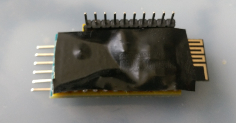 It's ugly but it's efficient :D
Common parts
This are the parts that are common to all sensors made with this shield
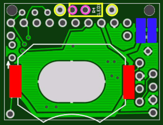
CR2032 battery
Soldered on the red color pads. It will not run without capacitors to backup the battery during high loads, and I only had space for SMD capacitors. So if you're allergic to SMD, use the through-hole battery holder & capacitor on the NModule board.
You should first solder the battery holder, it's a bit difficult because the holder is a big piece of metal and will absorb heat from your soldering iron. So I suggest the following process :
- increase temperature of your soldering iron
- put a blob of solder on the "legs" of the holder, as the holder is alone and not on the board you don't need to be afraid of excessive heat
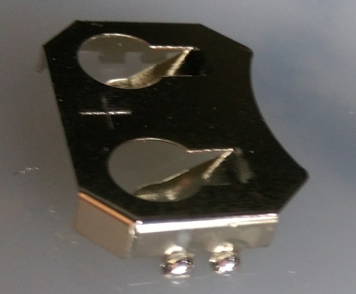
- put back your soldering iron to normal temperature
- put solder on ONE pad of the board, be generous
- move holder in place with plyers, at the same time melt the solder on the pad with your soldering iron so the holder legs are tight on the PCB pad and not floating in the solder. When holder is in place remove soldering iron to let solder solidify while keeping holder in place with your plyers
- on the other side you will just need to put solder on the pad and melt it, while pressing on the holder with your plyers so that it's legs stay firmly on the pad. Keep pressing after removing the soldering iron until solder solidifies.
After holder is in place, solder the reserve capacitor(s)
You can put some SMD (1206) ceramic capacitors or an electrolytic through hole capacitor.
SMD capacitors are on the blue pads. You should have at least 100µF but the closer you are to 200uF the better it is. I suggest to use ceramic capacitors of 100µF each, if possible X7R, with the voltage bias with 2*100uF it gives me a real capacity of 130µF so there's not much margin. You can find up to 220uF in 1206 size so in that case one is enough.
Through hole capacitor in pink color. I've been happy with 10V / 220uF capacitors so I advise you to use the same. Using a low voltage rating means a reduced size and 220uF ensures a good reserve to help the battery during high load.
LEDs
You have 3 options here:
- no leds
- SMD leds
- Through hole led
For the 1st and 2nd choices, you don't need the upper part of the PCB so you can save a bit of sensor space by cutting the top part of the PCB with scissors along the red dashed line. If you are planning to do a door sensor with a reed switch it will also be easier if you cut this extra part.
On most of the NModule shields, green led is A1 pin, red led is A2 pin. These are analog pins but they can also be used as digital pins, just set the pin mode as output and then use digitalWrite.
SMD LEDs
These are clearly labelled on the PCB with "green" and "red" texts. For both the led is on the left, and the resistor on the right. So red led is on red color pads, its resistor is on clear red pads. Green led is on green color pads, its resistor is on clear green pads.
Through hole LED
For this I am using a 3mm Green + Red led with common cathode. It will go in the holes circled in clear blue. Cathode is the longest leg in the middle, and you can't mix between green and red as I put some lines on the board next to green and led texts: short line for green color which has the shortest leg, longer line for red color. I had space for only one resistor (Yellow on the pictures) for both colors, so you will have to chose a value that will fit both colors, 330 or 220 Ohms are ok.
Reset button
In case you find more convenient to have reset button on the front, you can unsolder the reset button on your ProMini and solder it in the front, in the purple color footprint. If you are not using the cheap "the simple" ProMinis from AliExpress or Ebay you might have a different switch, in that case you can buy them for a very low price, just over 1$ for 100 on AliExpress.
Door sensor
With normally opened and normally closed reed switch

This type of reed switch has pins for both states: by connecting each of them to the interrupt pins and enabling the interrupt only on the unconnected pin, we can achieve extremely low power, and we don't need any extra resistors, the pullup resistors of the atmega328 are enough.
Just connect the reed switch as illustrated on the picture above and you are good to go, you will just need to uncomment the #define REED_NONC line in the script to use it.
Advanced use
To enable easier placement of the reed switch on the side of the board, you can solder the NModule connector without the GND, D2 and D3 pins (circled in blue on the picture above). Then use the pins of the reed switch to connect NModule and sensor shield.
With normal reed switch

Connect Reed switch between GND and D3 (red color). Then you can use either an SMD resistor (yellow color, marked R3) or a through hole resistor (pink color, holes marked R3')
Advanced use
To enable easier placement of the reed switch on the side of the board, you can solder the NModule connector without the GND and D3 pins (circled in blue on the picture above). Then use the pins of the reed switch to connect NModule and sensor shield.
Temperature, Humidity, Light and other I2C sensors
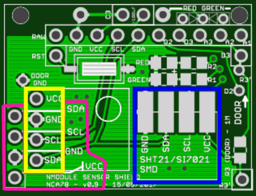
SMD SHT21/SI7021
Blue color. This is the SMD version of the breakoutboard for SHT21/SI7021. I strongly advise you to buy that version, even if it's a bit more expensive, because it's much more simple than the other breakout boards and there's no voltage regulator meaning no wasted power. Of course if you're not running on battery and your VCC is 5V and not 3.3V or lower, do not use this, use the "classic" breakout board !
No special instructions are needed here, if you have already soldered the radio on NModule it's the same process, but easier: the pads are wider and it is really easy :)
Other I2C sensor
These are in yellow and pink color. I used what I think are the 2 most common I2C pin orders so you should be able to use most of the temp/hum/light/UV I2C sensors out there. Just check the breakout boards you are orderings to make sure they match one of these 2 pin orders. Some breakout boards have extra pins for address selection or interrupt, but the main pins for power and I2C communication are enough to use them.
If you have I2C sensors that cannot fit that board, don't hesitate to share in the comment and I might add support in a next revision.
3D printed enclosure
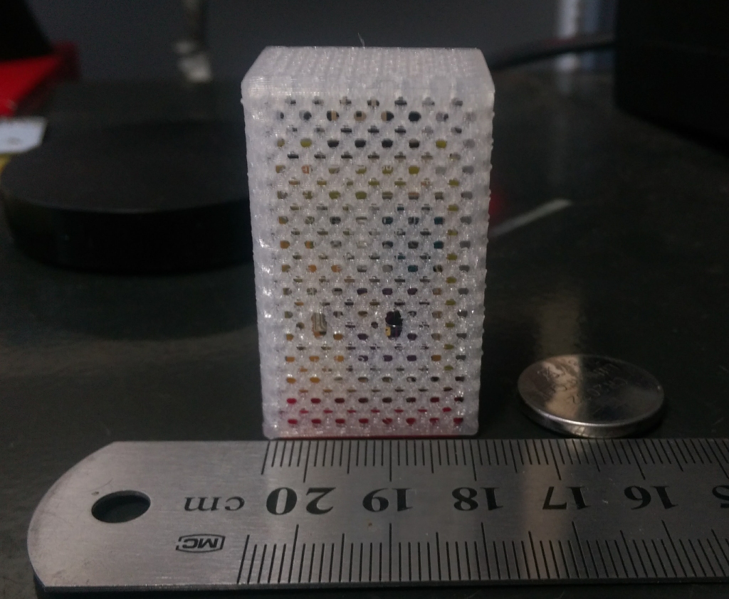
I am working on some 3D printed enclosures for the full sensors, I'm not ultra talented as a designer :D but at least it will provide a good base for others to improve. I'm waiting for the last release of PCB from PCB house to arrive to make some final version.
| Part | Value | Device | Package | Description | AliExpress link |
|---|---|---|---|---|---|
| BAT1 | 20mm coincell | BATTERY20MM_4LEGS | BATTCON_20MM_4LEGS | Battery Holders | https://www.aliexpress.com/item/50pcs-SMD-Tab-20mm-CR2032-2032-Battery-Button-Cell-Holder-Coin-Cell-Retainer-Battery-Holder-surface/32732961416.html |
| C1 | 100uF | CAP1206 | 1206 | SMD Reserve capacitor | |
| C2 | 100uF | CAP1206 | 1206 | SMD Reserve capacitor | |
| C3 | 220uF 10V | ELECTROLYTIC CAPACITOR | CAP-PTH-SMALL | Reserve capacitor | |
| R1 | 220-330R | R_0805 | R_0805 | SMD (0805) Resistor for green led | |
| R2 | 220-330R | R_0805 | R_0805 | SMD (0805) resistor for red led | |
| R3 | 1M | R_0805 | R_0805 | SMD (0805) Resistor for reed switch | |
| R4 | 1M | RESISTORPTH-1/4W | AXIAL-0.4 | Through hole resistor for reed switch | |
| U$2 | REED_SWITCH_NO_NC | REED_SWITCH_NO_NC_LONGNOCREAM | REED_NO_NC_NOCREAM | NO+NC Reed switch | https://www.aliexpress.com/item/20pcs-lot-3-pin-Reed-Switch-2-5X14MM-GLASS-Green-3-pin-Normally-Open-and-Normally/32507762756.html |
| U$3 | BME280_SHT21SMD_SI7021 | BME280_SHT21SMD_SI7021 | I2C_BREAKOUT_SHT21_SMD | SMD I2C breakout board for SHT21/SI7021 | https://www.aliexpress.com/item/Industrial-High-Precision-Si7021-Humidity-Sensor-with-I2C-Interface-for-Arduino/32524005324.html |
| U$4 | BME280_SHT21GY21 | BME280_SHT21GY21 | I2C_BREAKOUT_BME280_SHT21 | I2C breakout board for BMP180, BMP280, BME280, SHT21/SI7021 | |
| U$5 | SWITCHPROMINI_RESET | SWITCHPROMINI_RESET | SWITCH_SMD_PROMINI_RESET | SMD mini switch | https://www.aliexpress.com/item/100PCS-Lot-3-6-2-5MM-3X6X2-5MM-Tactile-Tact-Push-Red-Button-Micro-Switch-Momentary/32660690016.html |
| U$7 | LED | LED_0805 | Green color 0805 led | ||
| U$8 | LED | LED_0805 | Red color 0805 led | ||
| U$9 | CONNECTOR_4DUPONT | DUPONT_4 | I2C breakout board | ||
| U$12 | LED-DUALCOLOR3MM-THROUGH-HOLE | LED-DUALCOLOR3MM-THROUGH-HOLE | LED-DUALCOLOR-3MM | Green + Red LED, common cathode | https://www.aliexpress.com/item/X153-10pcs-LED-3mm-Round-Diffused-Red-Green-two-Color-Common-cathode-LED-Diode-Light-Emitting/32659046735.html |
| Name | Size | # Downloads |
|---|---|---|
| NModule_TH_Door.GBL | 34.29 kB | 1948 |
| NModule_TH_Door.GBO | 11.14 kB | 1895 |
| NModule_TH_Door.GBP | 9.03 kB | 1941 |
| NModule_TH_Door.GBS | 9.92 kB | 1916 |
| NModule_TH_Door.GML | 8.79 kB | 688 |
| NModule_TH_Door.GTL | 35.77 kB | 1951 |
| NModule_TH_Door.GTO | 48.12 kB | 1908 |
| NModule_TH_Door.GTP | 14.53 kB | 1956 |
| NModule_TH_Door.GTS | 10.09 kB | 2025 |
| NModule_TH_Door.TXT | 737 B | 514 |
| NModule_TH_Door.brd | 55.79 kB | 2073 |
| LICENSE.pdf | 95.73 kB | 480 |
| PRODUCT.txt | 110 B | 494 |
| COPYRIGHT.txt | 428 B | 489 |
| License_howto.pdf | 55.06 kB | 374 |
| Name | Size | # Downloads |
|---|---|---|
| NModule_TH_Light_SHT21.ino | 14.31 kB | 2078 |
| Revision | Created | Layers | Dimensions |
|---|---|---|---|
| rev1 | 9 years ago | 2 | 31 × 23 |
